


Revit. Walls Reinforcements. Why non-editable rebar shapes are created and what to do about it
One of the most common questions when working with the Walls Reinforcement function is something like this: "Why after the plugin does not work to edit the shape of the rebar? In this case, the document has already the shape of the rebar, but the plugin has created a new non-editable". It's time to look into this matter.
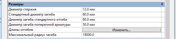
Let's start with the fact that the types of rebar have the property “Standard bend diameter”:
This property allows us to create rebar shapes without radii in the sketch and create the shape as simple as possible – straight sections. And Revit itself will have to add bends. For example, look at the sketch of the U-shaped rebar:
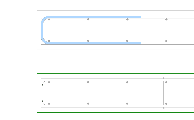
As you can see, the shape sketch has no fillets and consists of three straight segments.
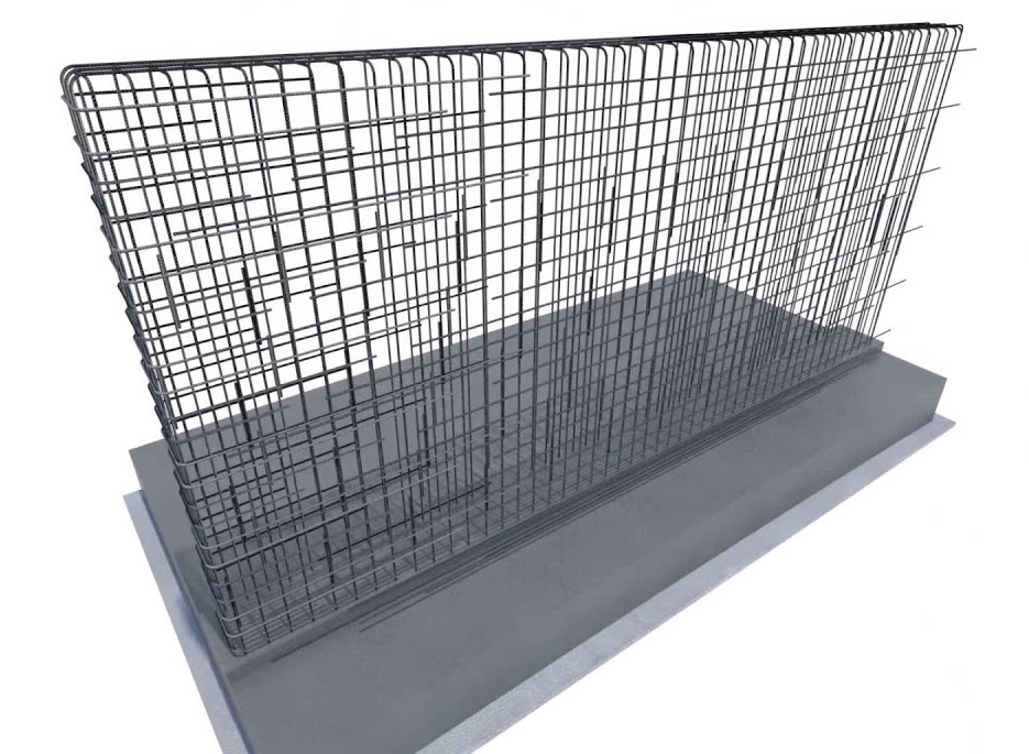
Before moving on to the studs, which are the most common problems, you should explain how the reinforcement works in the Walls Reinforcement function: the function calculates the required shape of the bar along the middle lines – i.e. it is the same sketch. Then the method of creating a reinforcing bar from Revit API is called and the magic begins – Revit itself selects the shape of the rebar from the existing ones in the project, comparing the sketch. The number of segments and their position relative to each other must be the same. That is, the lengths of these segments are not affected. Accordingly, when creating a U-shaped bar Revit without any problems will take this form:
The number of segments is the same (3 pieces) and the position relative to each other is also the same (form the letter U).
But if there is no suitable form in the current project, Revit will create it itself. However, it cannot be edited! And it doesn't depend on the function – it's such a feature of Revit. Although in most cases, these shapes become editable when you load existing rebar shapes into the project. But not always.
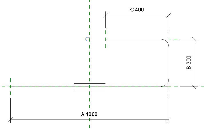
And finally we turn to the stirrups. Since the property "Standard bend diameter" allows you to create shapes with simple sketches, it is logical that everyone uses this feature. Also, do not forget that in Revit you can use bends at the ends of the rod. Here, for example, looks like a pin shape in a fairly common template:
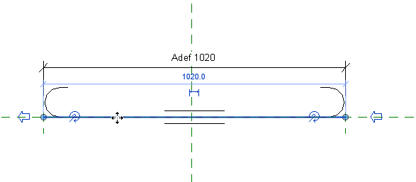
A shape sketch consists of only one straight segment using hooks at the ends. When designing the functions Walls Reinforcement were weighted the pros and cons and decided not to use hooks. One of the reasons - they (hooks) will not appear in the statements.
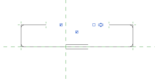
Another option – the shape of the stirrup without hooks. Something like that:
But both presented options will not be taken when the stirrups will be created by the Walls Reinforcement function! The fact is that the geometric shape of the stirrups is calculated by the function in as much detail as possible, taking into account the bend rates. It is this detailed design allows you to "put on" the stirrups on the horizontal and vertical reinforcement with maximum accuracy. When this is the geometric form is transmitted to Revit for create, then it looks like this:
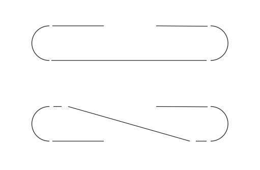
I specifically added breaks to show the number of segments used when creating stirrups.
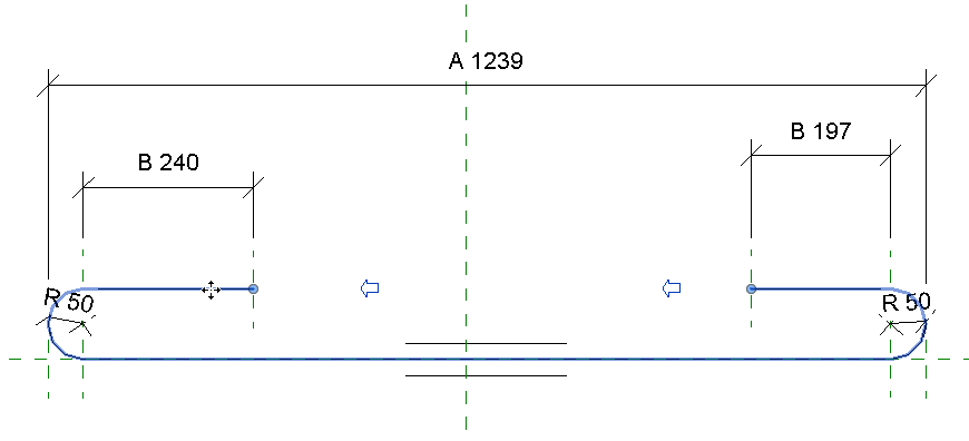
Thus, usually no one has the desired shape of the rebar in the project and Revit creates it itself, making it non-editable. To avoid this problem, the form must be initially created in the project. As I wrote above-the main thing is to match the number and sequence of segments. This form of rebar (2017 version) was made in just a few seconds, and it is "picked up" by Revit when creating stirrups by Walls Reinforcement function:
I hope this article will explain once and for all how rebar shapes software works and why they are not editable.