Icon
Related news and articles
Using
Align
Alignment of MEP curves
After starting the command, you must follow the steps to select elements in sequence:
Select the reference MEP curve for alignment – select the element relative to whose axis the alignment will be performed.
Select the MEP curve to be aligned – select the element to be aligned to the axis of the previously selected element.
The command also processes the previously selected element – if an element is already selected in the model at the moment the command is run, it automatically becomes the reference MEP curve, and it remains to select the element to be aligned.
There are three possible applications of the command:
- alignment of two elements along the same axis
- alignment of a non-vertical element to the axis of a vertical element
- alignment of a vertical element to the axis of a non-vertical element.
Multibuilding
Multibuilding of MEP curves
After starting the command, you must follow the steps in sequence to select the elements:
Select MEP curves – selection of elements from which to multibuild. The plugin processes elements that are parallel in the current view. When the plugin is running on the plan, the elements are allowed to have a slope.
Select the base MEP curve – select the element, for whose axis the point of further construction will be specified. Other elements will be built parallel to the selected one.
The command also processes preselected elements – if at the moment of command launching there are already selected elements in the model, you should specify which of them will be the base MEP curve.
After selecting the elements to be processed, the window of setting the allowable angles between the elements to be built appears:
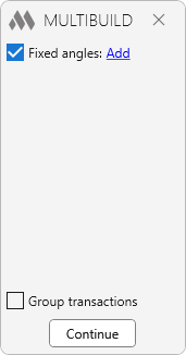
In this window you can set a fixed value of angles between elements during construction (in the range from 10 to 90 degrees). Fields for setting angles are added using Add:
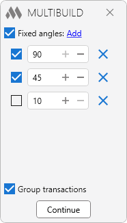
In this case, the closest of the specified angles is selected and the drawing is performed at this angle to the specified point. The element from which the drawing is performed can be lengthened or shortened.
If the Fixed angles option is disabled or if no angle value is added or checked, the drawing is performed directly from the end of the outermost element to the specified point at an arbitrary angle (in the range from 10 to 90 degrees).
Group transactions – this option allows combining the result of building into one transaction, i.e. the plugin result is canceled when canceling one last action (Ctrl+Z). If the option is disabled, each action performed after clicking Continue is canceled separately.
After clicking the Continue you will enter the mode of direct construction of elements.
Select a point – specifies the point where the base MEP curve should arrive. The command works cyclically until Esc is pressed.
At this stage the following actions can be performed:
- Constructing a new system element up to the specified point.
If the endpoints of the selected elements are located on the same line, then after you specify the point, the new element of the system will be drawn from the end of the existing element to the specified point.

- Aligning the end points of the current elements
If the endpoints of the selected elements are not on the same line, after specifying the point, the ends of the elements are aligned to the position of the point. The next point you specify defines the drawing of the elements.
- Canceling the last construction
In order to cancel the last construction, you must click on the area behind the created elements. Then you can continue the construction.
- Changing the length of elements
In order to change the length of the outermost elements you should put a point at the required distance on any of the elements or in the space between them.
Set Distance
Setting the distance between MEP curves
After starting the command, you must follow the steps to select the elements in sequence:
Select MEP curves – selection of elements between which you want to set the distance
The command also processes preselected elements.
After selecting the elements, a window with distance settings appears:
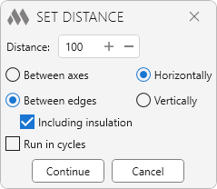
Distance – field for specifying the value of distance between elements
Between axes – the distance will be set between the axes of the selected elements.
Between edges – the distance will be specified between the edges of the selected elements.
Including insulation – this option is available only in the Between edges mode. If this option is enabled, the thickness of the element insulation will be taken into account when specifying the distance.
Horizontal – the distance between the elements will be specified horizontally.
Vertical – the distance between the elements will be set vertically.
To determine the direction of the offset (e.g. vertically up or down), it is necessary that there is a minimum distance between the elements in the desired direction. If there is no minimum distance between the elements in the desired direction, the plugin will shift the curves relative to the plane of their location.
After making the settings, you should click Continue and perform the following action:
Select the base MEP curve – select the element, relative to which the specified distances for the other elements will be counted.